High ceilings and reflective surfaces create a reverberant space that can lead to intelligibility and clarity issues. Instructors require high impact music to energize their classes.
Midtown Athletic Club
High ceilings and reflective surfaces create a reverberant space that can lead to intelligibility and clarity issues. Instructors require high impact music to energize their classes.
Midtown Athletic Club
High ceilings and reflective surfaces create a reverberant space that can lead to intelligibility and clarity issues. Instructors require high impact music to energize their classes.
Midtown Athletic Club
High ceilings and reflective surfaces create a reverberant space that can lead to intelligibility and clarity issues. Instructors require high impact music to energize their classes.
Trial and error, plus a willingness to walk around and kick boxes
a few feet this way or that, can make a big difference.
By Bennett Prescott
No items found.
“Run & Gun” Subwoofer Arraying Techniques
Trial and error, plus a willingness to walk around and kick boxesa few feet this way or that, can make a big difference. By Bennett Prescott
Of all the tweaking I do as a system tech, the most common is fixing mediocresubwoofer setups. Problems in this area are so prevalent that many audio professionals take them for granted or assume there is no room for improvement.
However, there is often a better solution, and further, it’s usually free ofcharge and can be accommodated by most system layouts. Let’s have a lookat subwoofer response in a free field (i.e., outdoors) to observe how commonsubwoofer setups can offer inadequate coverage and to discuss ways they canbe improved.
First, a quick primer on how a sound wave operates. Typical subwoofer frequencies range from 30 to 120 Hz, a span of two octaves that corresponds towavelengths from 38 feet to 9 feet. Why is wavelength significant?
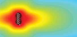
Figure 1
Figure 1 represents a common omnidirectional subwoofer. Because thissingle sound source is acoustically “small” relative to the size of the waves itreproduces, it has negligible effect on them.
A source is acoustically small when no dimension of the source is largerthan one-quarter wavelength at the highest relevant frequency. Any smallsource will exhibit near-omnidirectional response. This makes it very predictable and easy to work with, and fortunately most individual subwoofers meetthis criterion.
Pattern Narrowing
Unfortunately, there is no single subwoofer that has enough output for evenmoderately sized events, so you’re going to have to use a lot of them. Whenyou take a perfectly good subwoofer that has a lovely omnidirectional patternand place it next to two, four, eight or more of its peers, the resulting arrangement no longer has an omnidirectional pattern.
Figure 2
What happens is that the dimensions of the subwoofer array have becomeacoustically “large,” and the collection of sources are no longer within onequarter wavelength of each other. The increasing size of the array causessomething called pattern narrowing, demonstrated in Figure 2 using two andfour subwoofers.
To understand why this narrowing occurs, it helps to have a working knowledge of phase. Phase is the time offset between two waves, measured indegrees, as shown in Figure 3.
If you imagine a wheel, one full turn of the wheel would be 360 degrees ofphase, or one full cycle of the wave. Half a revolution would be 180, or halfthe wave, and so on. The behavior of two waves interacting depends on theirphase relative to each other. That is to say, two waves perfectly in phase(0 degrees difference) will add coherently, for 6 dB of gain. Two waves 180degrees out of phase will cancel perfectly.
Figure 3
Any other phase relation will result in somewhere between perfect additionand perfect cancellation. Most importantly, up to 90 degrees of phase deviation will result in between 3-6 dB addition, and 120 degrees will result in nolevel difference (0 dB).
As long as the phase difference between two sources can be kept within120 degrees there will at least be no loss in level, so this should be our goal.Crossing over the 120-dgree precipice results in rapidly increasing cancellation until 180 degrees is reached and the two waves cancel completely, sothis region is to be avoided at all costs!
Time & Cycles
Phase can be a difficult concept to grasp because we are used to thinking oftime differences in milliseconds (ms). To think in terms of phase, you need toconsider frequency, i.e., how many cycles the wave goes through in a givenperiod of time, as they are interrelated. A 60 Hz sine wave is about 19 feetlong, and takes about 17 ms to complete (1/60 of a second).
For example, if we have two subwoofers spaced 3 feet apart, how differentwill the phase of the first subwoofer’s wave be when it arrives at the secondsubwoofer, and will their energy add or subtract?
Table 1 shows us there will be about 60 degrees of phase difference, whichwill still result in over 3 dB of addition over a single subwoofer. Remember that this is only the difference at the second subwoofer’s location, which isthe worst case scenario. In any other direction the phase difference betweenthe two subwoofers will be smaller and cause even more addition, so at 60Hz this spacing will still result in a very smooth pattern.
Table 1 Determining Wavelength Wavelength is a function of frequencyand the speed of the wave in themedium it is traveling in. In thecase of sound waves, which moveat approximately 1,125 ft/sec indry 68 degree air at sea level, thefollowing function may be used:λ=V/ƒ where V = speed and ƒ =frequency. At 60 Hz, therefore,the wavelength of sound would be1125/60=18.75’.
Because the spectrum of live audio covers more than just 60 Hz, however,it is critical to view its operation at more than one frequency. If we view the same example from the last paragraph at 120 Hz — twice the frequency and therefore twice the phase shift over the same distance — things havechanged significantly.
Table 1 also shows that at 120 Hz there will be 120 degrees of phase difference for the same 3 feet of spacing, which results in no addition and mightindicate that this spacing is becoming problematic. Of course, there may beno audience members in the area of no addition, which might make it a nonissue for your application. (In very wide venues or venues with wraparoundseating, for example, this could be trouble, but perhaps not for the majority ofaudience arrangements.)
Limited Control
With the math out of the way, we return to the subject at hand: why subwoofer arrays behave the way they do, and how to make this behavior workin our favor. Ideally, we would set up our subwoofer array so that it producedeven response with perfect addition everywhere in the audience area, andperfect subtraction everywhere the audience isn’t.
This would be wonderful, but in the real world we have a limited amount ofcontrol over these long low-frequency wavelengths. What control we do haveis directly proportional to the length of our array, which is a double-edgedsword. As our array grows it becomes acoustically “large” and its patternstarts to narrow, but at the same time we have more control and can use several techniques to rearrange the pattern so it works better for us.
Figure 4
Figure 4 shows a typical left/right stacked subwoofer setup at 60 Hz. Downthe center line of our imaginary audience. the sound from both subwoofersarrives at the same time, or with very little phase difference, and exhibitsnear-perfect summation. This is where the term “power alley” comes from.
As you walk off-axis, however, you are “walking around” the phase wheel,one subwoofer’s signal relative to the other. Energy now arrives 90 degreesout of phase, then 120 degrees out of phase, and finally you walk into thedark zone where the two signals approach 180 degrees phase difference andcancel each other. Depending on the frequency, more than a third of youraudience might as well have no subwoofers at all!
This situation cannot be fixed by turning up the subwoofers or equalizingthem, the problem is caused by time arrival differences. To fill in those darkareas another subwoofer setup must be considered.
Figure 5
Making It Wider
Looking back at Figure 2, we can begin to see a solution. Putting all of thesubwoofers together yields a much more consistent pattern throughout theaudience area.
Unfortunately, as subwoofers are added to meet our output needs, thecoverage pattern narrows. Figure 5 shows a 6-foot-long array, and while theresponse looks a lot better than our left/right subwoofers (Figure 4), it has narrowed to the point that some audience members will be out of the coverage before they are beyond the coverage of the main loudspeakers. This leavesmuch of the audience with mismatched low-frequency response.
However, “a little delay will do you.” This pattern widening technique workseither with electronic delay (Figure 6) or by physically moving the subwoofers (Figure 7). The major difference is that physical delay focuses the soundbehind the array (i.e., on stage) while digital delay affects both sides of thearray equally, widening the pattern behind and in front.
Figure 6
Since many of us aren’t carrying several extra channels of digital delay,or additional amplifier channels to use it, the physical solution is cheap andcheerful. I’ve reduced the arrival time difference for listeners off-axis withoutdamaging the response for those in the center of the audience.
By moving the outside subwoofers backward by as little as a foot and a half,the array’s pattern is substantially altered. You can experiment with varyingamounts of arc to meet your specific needs.
Figure 7
Other Avenues
There are a few other ways to attain better response than left/right stackedsubwoofers, even if you don’t have a whole lot of subs. Figure 8 shows onepossibility. I find that putting 50 percent of the subwoofers in the center is alarge improvement.
Figure 8
Another option is to spread out available subwoofers as shown in Figure 9.The predicted responses may not look as pretty as the center clustered subwoofer setup, but remember that we’re only looking at a single frequencyhere. The pattern will look very different elsewhere in the subwoofer array’sfrequency response, but either way it’s a heck of an improvement over “traditional” left/right stacked subwoofers.
Figure 9
These are just a few of countless ways to skin this cat. The best way to getbetter at subwoofer arraying is to do it a lot, and to experiment with prediction software. Trial and error, plus a willingness to walk around and kick boxesa few feet this way or that, will help you understand these systems better. Istill learn something every time I put a system together.
Next time I’ll be looking at directional subwoofer arrays and integrationwith the main PA.
Editor’s Note: Most of the images for this article were generated by G.P.A.2.2, a freeware product of Chilean coder Sebastian Rivas Godoy. For more infogo to http://gpa.hms2k.cl/. The phase shift graphic is courtesy of Wikipedia userPeppergrower.
BENNETT PRESCOTT is an independent engineer/technician specializing insound system design and deployment.